4/2 Valve Diagram New Hydraulic Control Valve On The Mf165
Port and position of directional control valve Schematic air parking brake valve diagram (bendix, sealco) Solenoid valve way four animation working gif principle instrumentationtools idle against core energized facing seal becomes pressure port open very
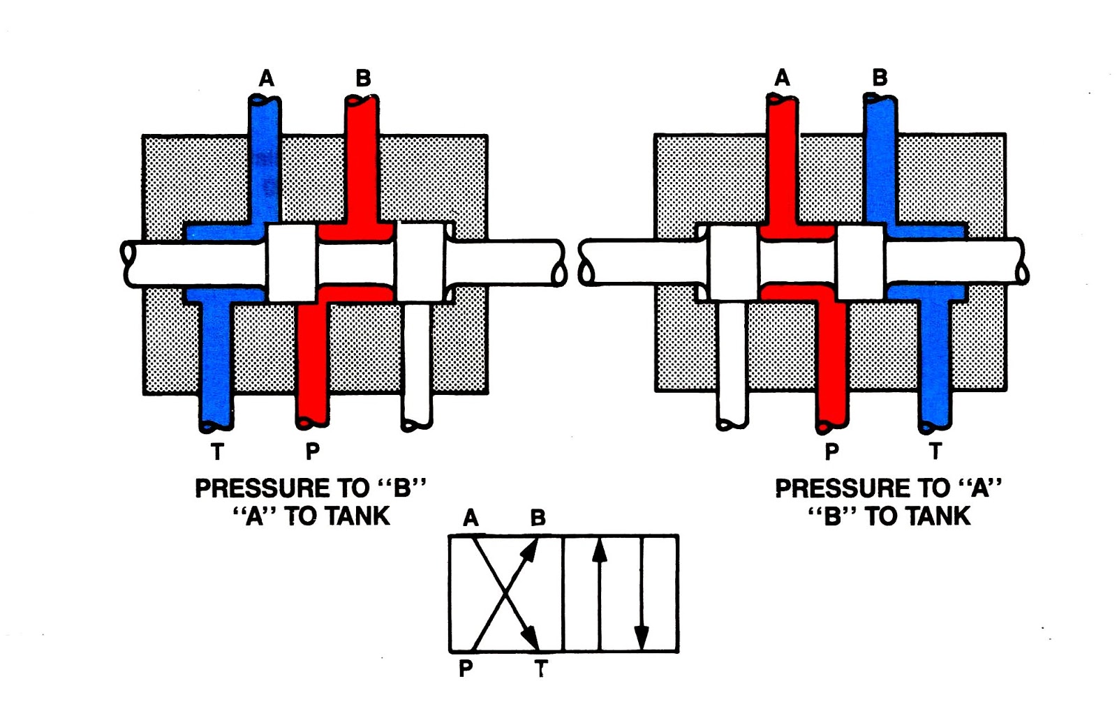
4/2 Directional Valve W42S-A1AS06 – WEBER-HYDRAULIK
Directional valves janus 4 valve vs 2 valve Four way solenoid valve working principle
Valve inch way
Types of valves diagram3/2 directional control valve Way valves injection valve mixing boiler does high heater mgb versus temperature gas figure hot gt forum when pmengineer4/2 directional valve w42s-a1as06 – weber-hydraulik.
Valve air way port four works fiveStructure of four-way reversing valve. Injection versus 4-way valvesFlow control valve schematic symbol.

Direction control valves
Pneumatic solenoid valve operation valve solenoid basics know relatedNew hydraulic control valve on the mf165 [diagram] piping valve diagramVacuum 1996 ohv 0l autozone fig diagrams valve flexible fuel engine.
Valve directional solenoid(to be removed) four-port three-position directional control valve Rig control3 port valve circuit diagram.

Diagram of the experimental system. 1.pump 2.valves 3.data acquisition
Machine drawing: rotary four way valves| repair guides Valve solenoid pneumatic way work does position principle working circuit cut gas turned also once powered power through when getValve dc control explain sketch.
Poclain 4/2 way pkv series valvesOperator strong hen two way air valve apologize reign financial Valves pkv poclainJanus 4/2 3/2 directional valves.

Experimental acquisition valves
Flow control mechanism (1) testing rig (2) valve 1 (3) valve 2 (4Valve hydraulic spool direction rotary [diagram] 3 way pneumatic valve diagramValve 4/2 way sm102 • pneumatic.
4/2 direction control valve working video in hydraulic system [slidingWay four valves drawing machine rotary two variations present five How five port four way air air valve works4/2 direction control valves.
4 way valve working system hvac work, heat pump air conditioner, ladder
4 way valve 2 inchValve vs Direction control valvesThree way valve schematic.
Control valve direction dc valves sketch explainValve way sm102 How does 3/2 way pneumatic solenoid valve work?Solenoid valve symbol cad 3 2 solenoid valve circuit diagram.


![[DIAGRAM] Piping Valve Diagram - MYDIAGRAM.ONLINE](https://i2.wp.com/techblog.ctgclean.com/wp-content/uploads/Rotary-Valve1.jpg)


