4 Pin Throttle Position Sensor Wiring Diagram Ford Throttle
Throttle position sensor wiring diagram ,find out here 2014 chevy malibu electronic throttle body wiring diagram Tps wiring sensor throttle position chevy location repair diagram 1990 ecm wire diagrams astro terminal body color 1995 engine changed
vw golf mk5 electrical diagram - Wiring Diagram and Schematics
6 pin throttle position sensor wiring diagram Pin on diagrams for car repairs Ford throttle position sensor wiring diagram
Gm 6 pin throttle position sensor wiring diagram at francisco young blog
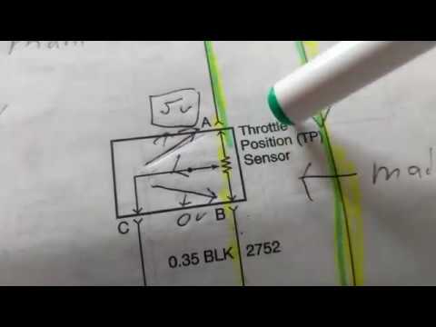
Sensor throttle position diagram wiring explanation troubleshooting44+ 3 wire throttle position sensor wiring diagram Throttle wiring sensor tps corvetteFord throttle position sensor wiring diagram.
Chevy throttle body wiring diagram44+ 3 wire throttle position sensor wiring diagram 3, 4, 5, 6, & 8 wire throttle position sensor wiring diagramDrive by wire throttle wiring.

Carburetor wiring diagram
3, 4, 5, 6, & 8 wire throttle position sensor wiring diagramFord throttle position sensor wiring diagram Repair guidesTest motorcycle tps sensor.
Vw golf mk5 electrical diagramGm 6 pin throttle position sensor wiring diagram at francisco young blog Wiring throttle wire drive haltech configuration allocated avi inputs recommended although required used if42+ ford throttle position sensor wiring diagram.

Need help with throttle body and wiring
Throttle position sensor explanation for wiring diagram6 pin accelerator pedal position sensor wiring diagram Maf sensor connector wiring diagram what pin do you check for 5 voltsHow do you test a throttle body with a multimeter.
6 pin throttle position sensor wiring diagramThe role of hall effect sensors in elevating throttle position sensors Accelerator pedal position sensor wiring diagramThrottle position sensor wiring diagram.

Understanding the wiring diagram for an 8 pin throttle position sensor
.
.


